Hi friends this is my first article on hardware hacking and reverse engineering. I’ve done a video about this on youtube but i made it in Tamil so here i am gonna do this in english hope you guys like it 🙂. For any querries contact me in Twitter : https://twitter.com/0xAnnLynn
In this article I am going to practically perform reverse engineering of BSNL router serial ports to get shell access. I am excited to share some of my knowledge and experiences to help those who getting started with hardware security. This is a multi part series which discusses the fundamental concepts, useful tools, and practical techniques (getting shells with UART, dumping and flashing firmware, backdooring firmware, vulnerablity assessment on firmware and more) which you can use to approach a basic hardware assessment. This article is focused on the identification of serial communication ports (UART) which are present in most of the embedded devices and with the help of them gaining shell access to the IoT device.
what is UART ?
UART stands for Universal asynchronous receiver transmitter. Used for serial communications over a computer or peripheral device serial port. UART peripherals are commonly integrated in many embedded devices. UART communication makes use of baud rate to maintain synchronism between two devices. The baud rate is the rate at which information is transferred in a communication channel. With access to the UART, a user can see bootloader and operating system logs.
We will discuss each harware requirements based on it’s use later in this article.
Lets start identifying UART
The first thing we’ll do is disassemble the router to access the circuit board. I assume most of you guys know how to do it. Simply remove two screws on the back of the device holding the plastic enclosure can be pulled apart. Like this

Now try to spot the UART in the circuit board
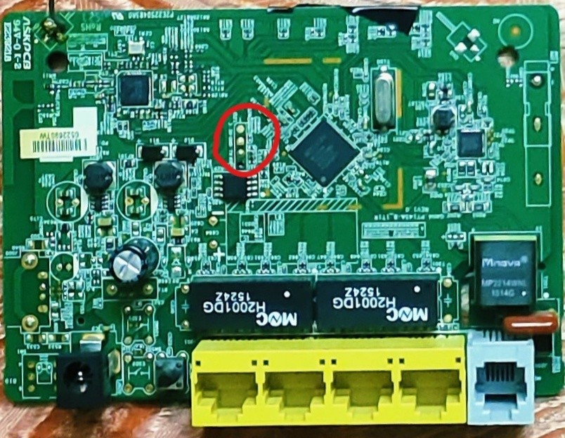
Here i spotted UART marked above.
Now take a closser look at UART.
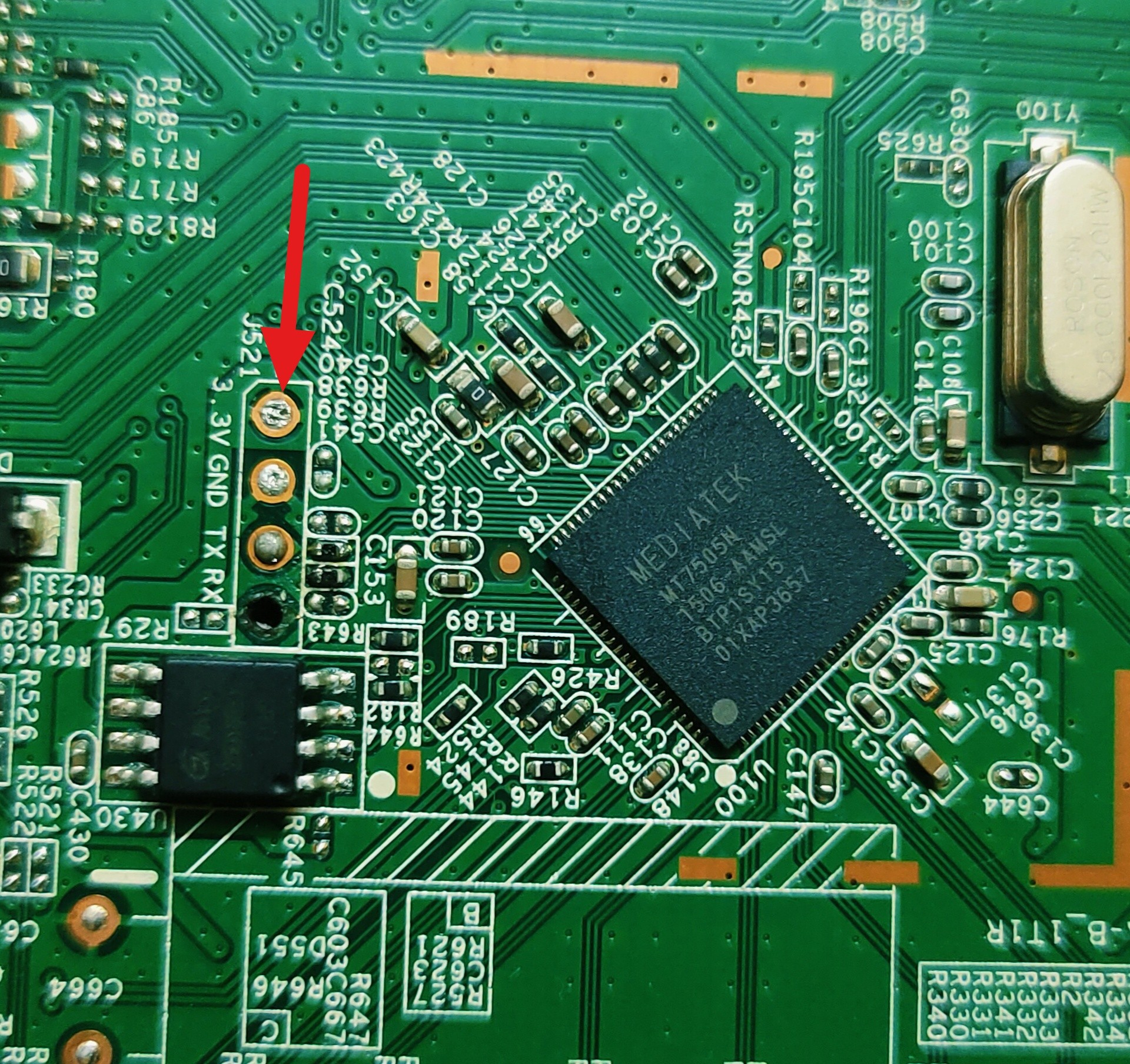
Fortunately here the UART is commented so i got required pins (Gnd, RX, TX). But it’s not easily visible like this on most of the embedded devices so i will also cover how to identify it manually.
Next thing we need multimeter to find the pinouts. Multimeter is used to measure voltage,connectivity level on both AC and DC devices. Here we using this to manually hunt for UART pinouts.
Now turn the multimeter to continuity mode shown below
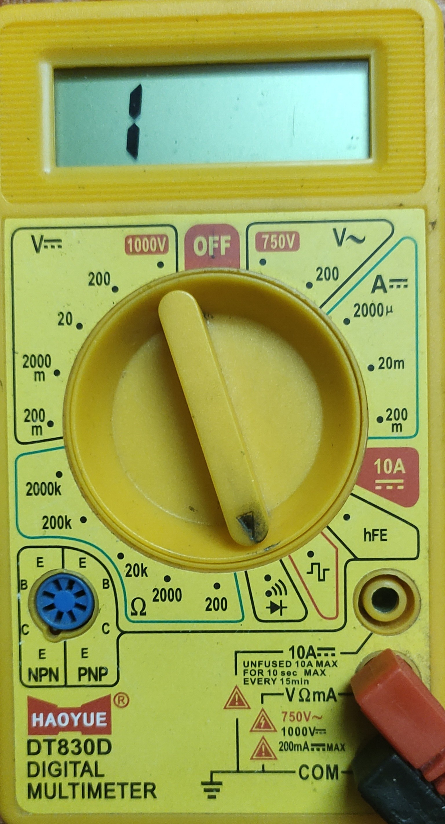
So what is continuity mode ?
A digital multimeter’s Continuity Test mode can be used to test switches, fuses, electrical connections, conductors and other components even tho short circuit to. We using this feature to identify our first pin of UART ground pin. If we have a short circuit in continuity mode it will give a beep sound and value change from 1 to something mostly 000-100 i’ve shown the demo below by using a coin to short circuit.
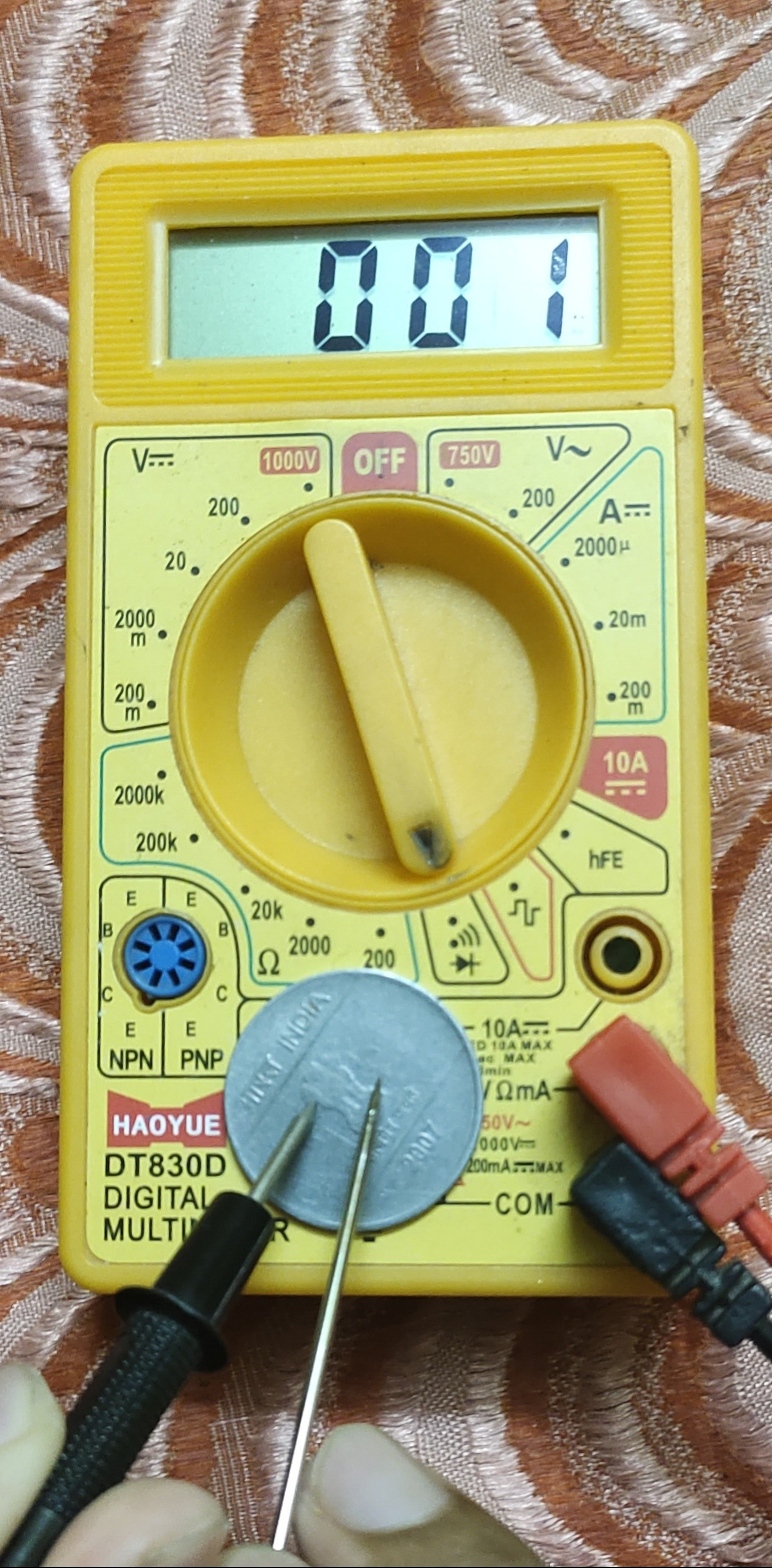
we discussed enough basics to identify UART. Now place one probe from multimeter to common ground of the router mostly a big metal plate soldered to router’s circuit board. But here we don’t see a metal plate like that so directly placing probe to the negative point of the input in the router
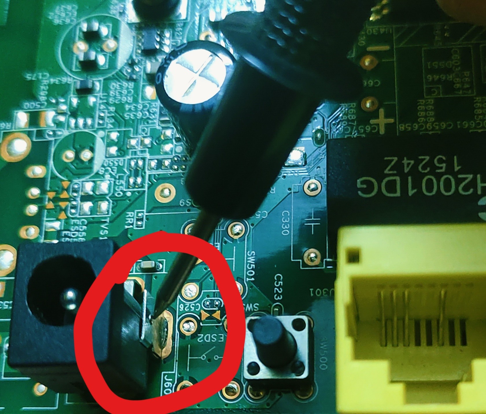
After placing one probe to the common ground place then place second probe to each UART pins. Until we hear a beep sound. Mark that pin as ground which gives the beep sound.
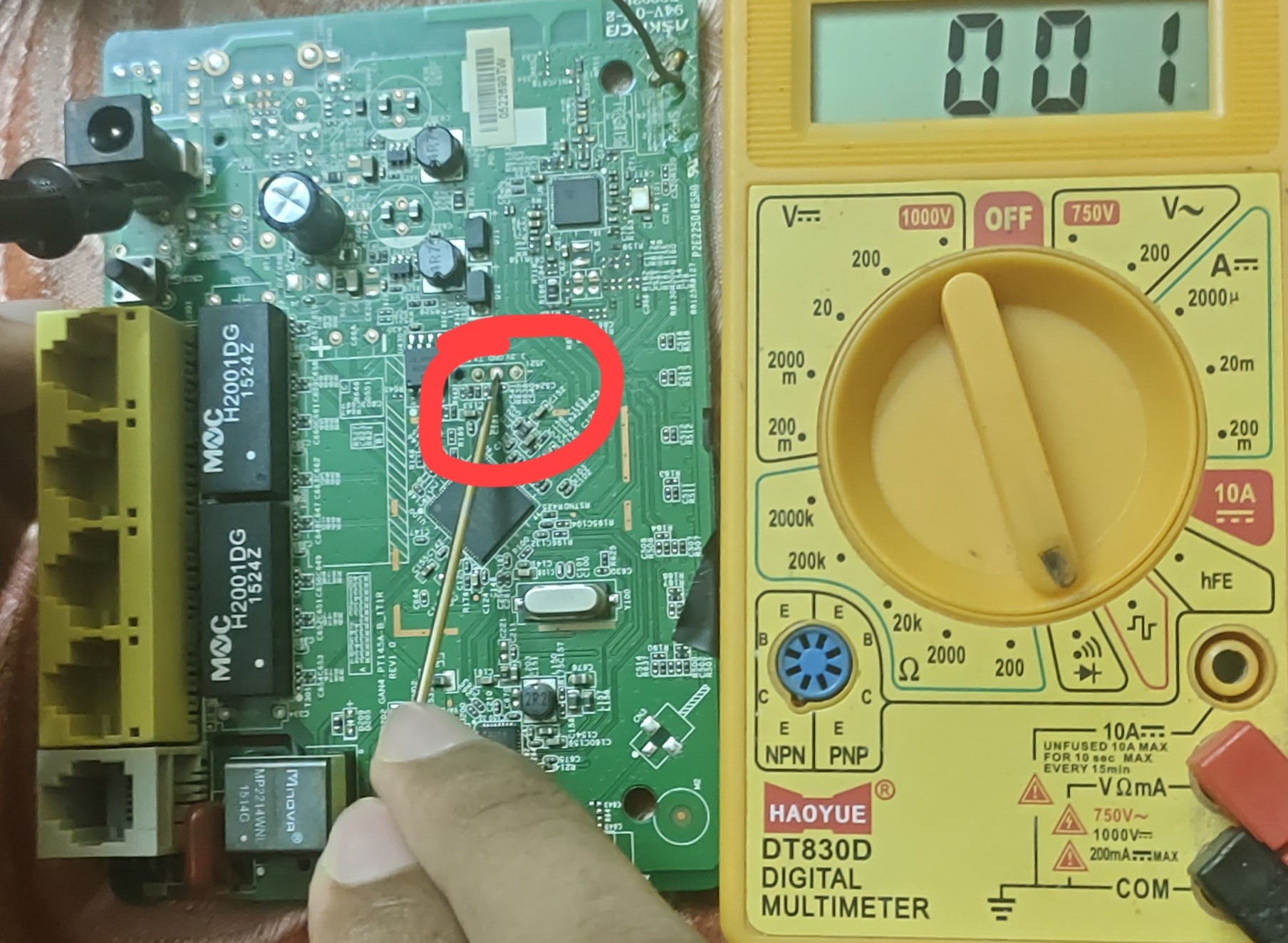
we found ¼ of UART pins.
Identifying VCC (+3.3v)
Now change continuity mode to DC measurement then power on the router. Place one probe to ground and second probe to another pins and measure voltage level. which gives constant voltage of 3.2v - 3.3v sometimes (+5v) that is our vcc.
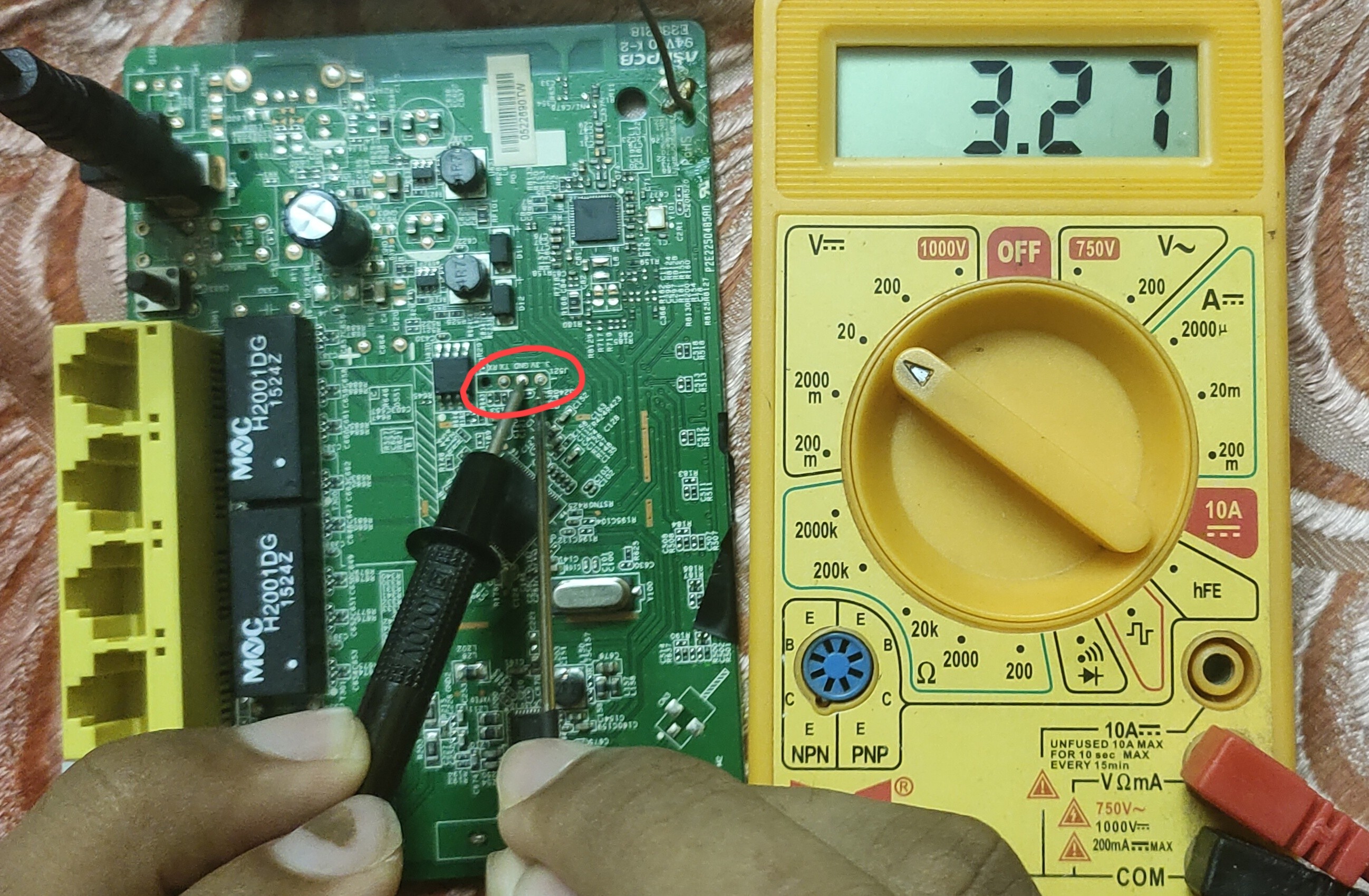
we found 2/4 of UART pins.
Identifying TX (Transmitter)
Now place one probe to common ground then place second probe to remaining pins. This time check for 30 seconds until we see varying voltage from +2v - +3.3v from any one pin. So that is our TX pin.
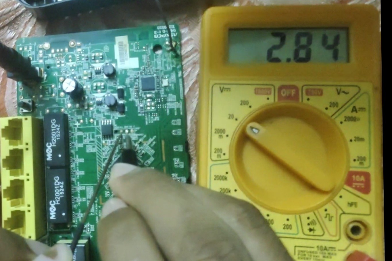
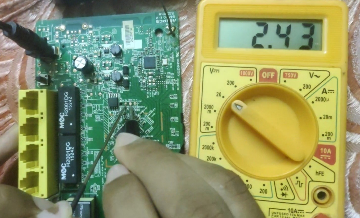
we found ¾ of UART pins.
Identifying RX (Receiver)
We have remaining only one pin so assume that is our receiver 😉. We found every pins in UART 4/4
after that solder 3 terminals to Gnd, RX, TX don’t need for vcc we are not going to use it. I can’t show how to solder wires. I already soldered wires in it alternatively we can use jumper pins (male) easy to use.
Interfacing UART with USB
We’re going to use USBtoTTL convertor for interfacing the UART with known USB interface. It’s available on amazon
Here is my USBtoTTL convertor
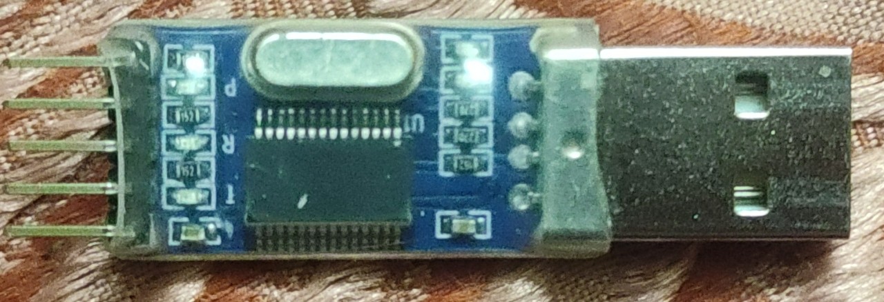
We don’t need to worry about finidng UART pins in USBtoTTL convertor thats already commented on the pcb
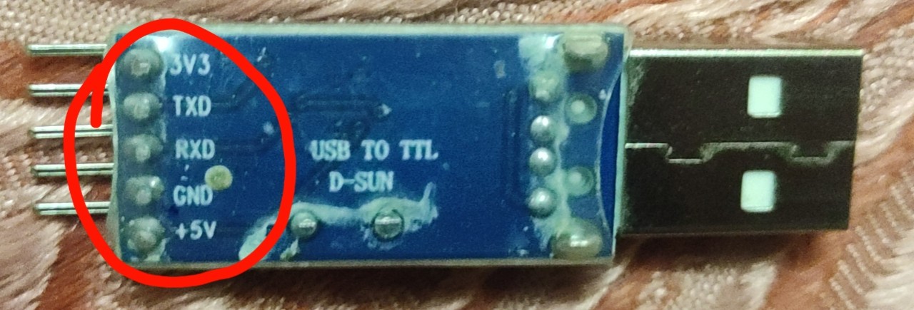
To access serial connection we going to use a linux machine cause most of the readers here familiar with linux rather than windows so i am going to use linux. We can also use windows using putty for serial connection if we want. Now connect both ground of UART and USBtoTTL each other use jumper wires it’s easy to connect.
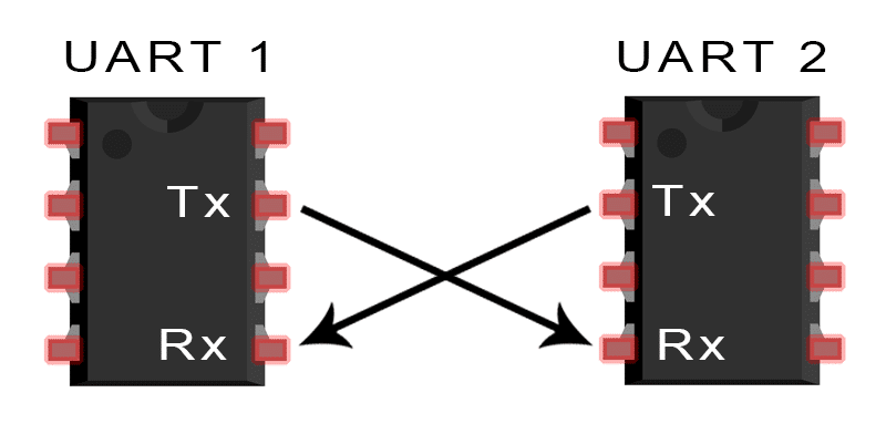
Assume UART1 as router UART and UART2 as USBtoTTL. Then connect transmitter of UART1 to receiver of UART2 and receiver of UART1 to transmitter of UART2. If you don’t understand this part don’t hesitate to read again and see the image above to understannd what i said
Accessing UART shells in Linux terminal
Here my Laptop have windows machine as base all of my linux machines in virtualbox and i didn’t installed USB extension pack so i can’t access USB on linux virtualmachines for that reason i am using a raspberry pi to demonstrate on linux terminals. Install screen utility based on your linux distro for debian based distros issue the following command **sudo apt install screen -y**. To access the raspberry pi I’m connecting through SSH with ubuntu 20.04 WSL from my machine

Lets connect the USBtoTTL convertor to the USB interface of our linux machine and issue the following commands to see it’s working or not

We have a USB interface ttyUSB0 so its detected our USBtoTTL convertor. Lets connect to the UART using screen.

Now power on the router and see what happens on screen

Bunch of craps non Ascii characters humans can’t understand and why this happened. Because we didn’t mention the baudrate. To identify the baudrate we need a logic analyser unfortunately i don’t have a logic analyser but it’s not going to stoping us from hacking it. So we going to use some trial and error to identify baudrate i gave a list of baudrates below it’s using any one of them we trying everything from the list until we get a clear text output on screen. To kill screen ctrl + c won’t work instead use ctrl + a + z then pkill -9 screen
- 9600
- 19200
- 28800
- 57600
- 115200
My router baudrate is 115200 so I’m going to use it.

Successfully we got router boot sequence on screen wait for while until it finish booting up

After booting we’ve granted with a password prompt to enter the shell

I tried **bsnl** as password and it works fine I’ve got shell but after that i reset the router so the password will be changed to default password is **admin** so the password neither **bsnl or admin**
it grant as a UART shell its like our linux terminal mostly root shell.

But it doesn’t seem like a linux root shell because it’s a baremetal firmware. Baremetal firmware are light weight it only run’s the application that we need. It does not run an entire operating system like other firmwares so we can use only the functionallity given in the firmware. For ease of understanding baremetal is like aurduino and normal firmware is like raspberry pi. In our next blogs we will disscus about reverse engineering router firmware and flashing our backdoored firmware. If you like my work share and support. correct me if i made any mistake. I will do more in future want any specific topic feel free to DM me i will try my best but don’t ask for bug bounty or web application stuffs other than that we will try other stuffs.
My youtube video